
How to Repair Your Garden Tractor's Charging System
Engine Science: Repairing Your Tractor’s Charging System
Your tractor requires electricity to run and function. Electricity creates the spark for your ignition, powers your lights, lifts your attachments, turns on your PTO, and runs any other accessories you decide to add.
This article will explain the workings of a Stator Charging System and how to diagnose and repair any issues you encounter.
Your tractor’s charging system consists of the following components:
- -Stator Winding
- -Flywheel Magnets
- -Regulator/Rectifier
- -Ignition Key Switch
- -Battery
The Stator Winding is a copper winding that is mounted on the engine and is located under the flywheel. The flywheel magnets induce an alternating current of electricity in the stator winding, while your engine is running. This Phenomenon is observed in Ohm’s Law which states the relationship between Electricity, Magnetism, and Motion. Any one of these can be created by the remaining two. In the case of our charging system, the engine uses Motion, and Magnetism to create electricity.
The Flywheel Magnets are permanent magnets that are installed in alternating polarities. These are normally permanently affixed to the inside of the engine’s flywheel.
The Regulator Rectifier is an electrical device that converts the Alternating Current from the stator and turns it into Direct Current in order to charge the battery. It also serves to regulate how much direct current is allowed to pass through to the battery.
The Ignition Key Switch is a rotary switch that connects the charging system to the battery source.
The Battery is an electro chemical device that provides 12 volt direct current.
How it all works together:
While your engine is running, the flywheel magnets rotate around the stator winding. This induces 24 to 28 volts AC from the stator windings. This current then travels to the regulator/rectifier. Here the AC current is partially blocked so only half of the AC wave is allowed to pass through. The remaining current that passes through the regulator rectifier is in the form of direct current. This direct current passes through the charging terminal of the ignition key switch, and then flows to the battery, charging the battery.
Troubleshooting:
If your battery is not charging one or more of the above mentioned components could be at fault. When troubleshooting it is important to systematically approach the problem so no component is overlooked.
We suggest beginning with the components that are easiest to check.
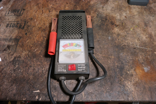
- 1. Battery: Perform a load test on your battery. An unhealthy battery will not take a charge. If your battery is more than 5 years old, you should replace it.
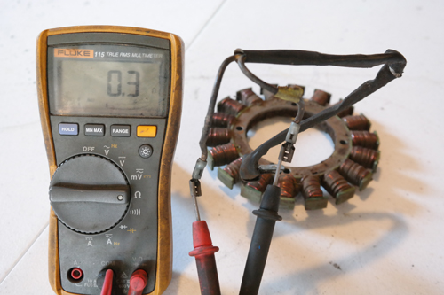
- 2. Stator: You can check your stator two different ways. 1. Take a resistance reading between the two terminals coming from the stator. A healthy stator will read a low resistance reading such as .1 or .2 ohms. Note: Be sure to account for the resistance that your multi-meter leads have, and subtract that from the final reading. If your meter reads 0, infinity, or open-line, the stator is defective and should be replaced. 2. The second way to test is to measure the AC voltage coming from the stator leads while the engine is running. A healthy stator should produce around 28 volts AC, when the engine is operating at full RPMs.
- 3. Regulator Rectifier: After confirming the stator winding is in good working condition, the regulator rectifier would be next to check. Remove the wire coming from the terminal marked B+. Measure the DC voltage coming from the B+ terminal of the regulator rectifier while the engine is running. If you show between 12 and 14 volts DC, the regulator rectifier is working properly. If you do not read any voltage at all, the regulator rectifier is at fault and should be replaced.
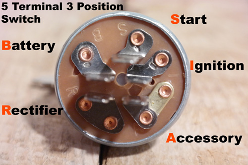
- 4. Ignition Key Switch: If everything checks out working so far, the last likely component at fault is the ignition key switch. Remove your key switch and use a continuity tester or digital multi-meter to confirm the terminals marked “R” (regulator/rectifier) are connected to “B” (Battery) terminal when the key switch is in the “on” position. If there is no continuity measured, the ignition switch is at fault
- 5. Flywheel Magnets: The flywheel magnets are typically not something that contributes to charging system failures other than falling off and breaking. If this happens, you can occasionally find used magnets on the internet, and they can be epoxied into place. If you cannot locate the magnets individually, a replacement flywheel would be the next best option.
- 6. Wiring: If all of the major components in your charging system test in good condition be sure to thoroughly inspect the wiring that connects all of the components together. Shorts, damaged wiring, blown fuses can all prevent your battery from charging.
In conclusion, your tractor’s charging system is a crucial system and is easy to troubleshoot and repair. Remember to go through your problem step-by-step and try not to make assumptions before testing. This will help you avoid purchasing costly parts unnecessarily.
Thank you for saving the Tractors!
- -Norman Ng
Recent Posts
-

Engine Science: Rewind Your Small Tractor Engine Stator - Charging System Repair
Engine Science: How to Rewind Your Statorby Norman Ng, Founder of iSaveTractorsYour engine’s stator …Sep 10th 2020 -

Engine Science: The Digital Multi-Meter
The ability to detect, observe, and measure electricity is crucial when trying to understand how a …May 7th 2019 -

5 Common Small Engine Rebuilding Mistakes
The engine is the heart of your garden tractor. When performing heart surgery on your tractor, be aw …Jan 4th 2019