
Engine Science: The Digital Multi-Meter
The ability to detect, observe, and measure electricity is crucial when trying to understand how a tractor works and learning what you can do to fix it. The digital multi-meter is like a doctor’s stethoscope. It allows us to see the invisible force of electricity and measure how it interacts with the components in our engines and tractors. A digital multi-meter measures current (amps), voltage (volts), and resistance (ohms).
For the sake of this article I am going to be focusing on digital multi-meters or DMM’s and not analog meters. DMM’s are readily available, easy to use, and easy to understand. You can find a good DMM at any store that carries tools such as Wal-Mart, Home Depot, Lowe’s, or at online retailers such as Amazon.
Digital Multi-Meters come in two common varieties: Auto- Ranging, and Non Auto-Ranging. A non auto-ranging meter requires you to select a range of “sensitivity” for the given function you are using. For example if you want to measure resistance, you would need to select a range of up to 200 ohms, up to 20Kohms (20,000 ohms), 200Kohms, etc. An auto-ranging meter will automatically figure out the range and give you a measurement.
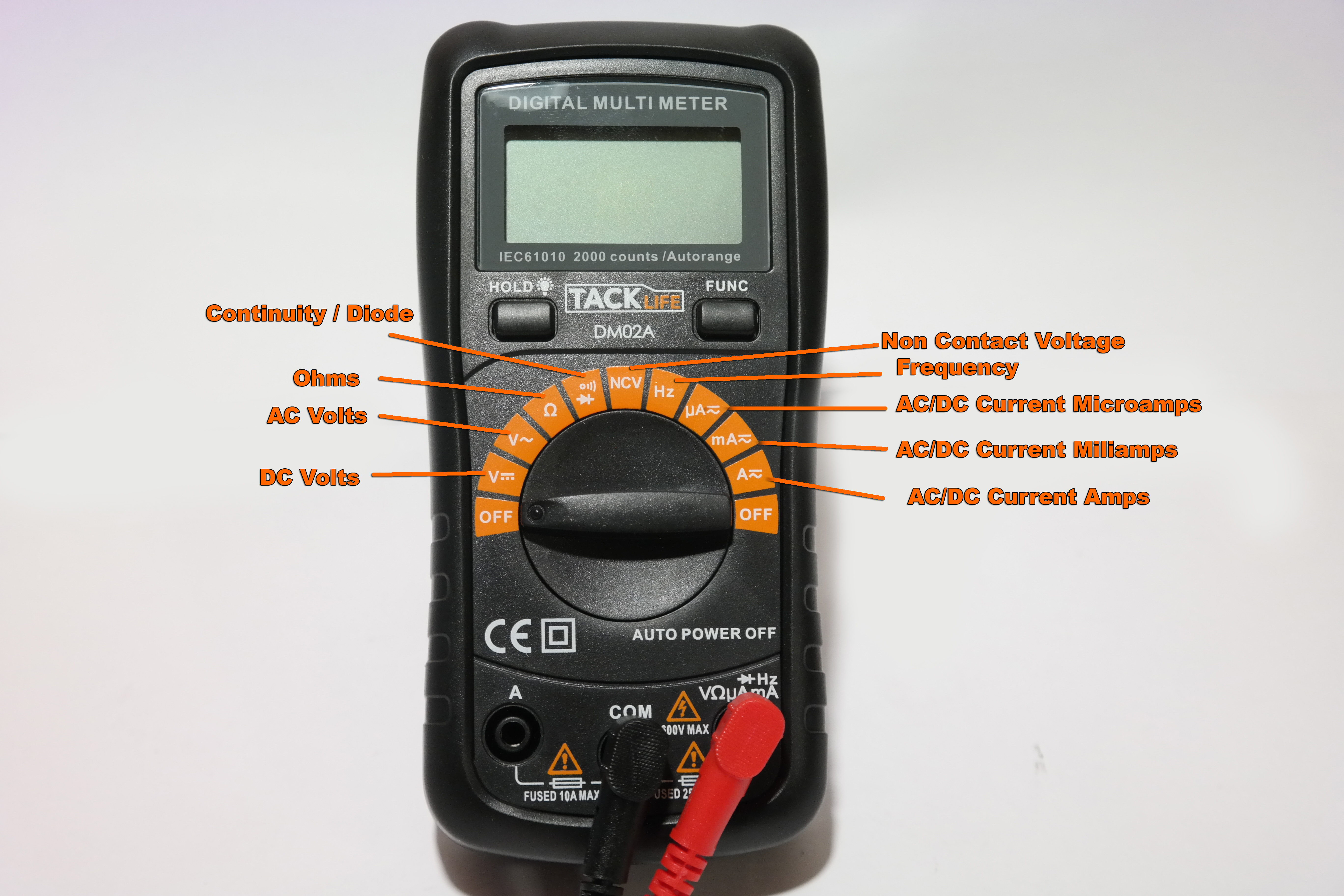
The Symbols on the Multi-Meter
V– stands for DC Voltage
V~ stands for AC Voltage
Ω stands for resistance in ohms
A- stands for DC Amps
A~ stands for AC Amps
m stands for Mili
M stands for Mega
µ stands for micro
Electrical Definitions:
Think of voltage as electrical pressure; amperage as the volume of electricity flowing; and resistance as electrical friction that resists current.
Direct Current or DC is electricity flowing from a battery. Alternating Current is electricity flowing from an alternating power source such as a stator.
Using the DMM
Before using your DMM plug the two probes into their appropriate places on the meter. The black probe will plug into the common port labeled “COM.” The red probe will plug into the “VΩµmA” port for most testing.
Measuring DC Voltage
Measuring voltage is one of the most common tests a tractor mechanic will conduct as he troubleshoots a system. The presence of the correct voltage will determine if a component is functioning correctly or not. A common voltage test will be of the battery. A healthy battery should read about 12.5 volts, and a battery that is being charged should measure between 13 and 14.5 volts.
To measure voltage on a battery for example you first turn your meter to DC Voltage. Place the red probe on the positive terminal of the battery and place the black probe on the negative side of the battery or on a common ground. Your voltage will display on the screen.
Measuring AC Voltage
To measure AC voltage for example on your engine’s stator, you first locate the two wires coming from the stator. Turn your DMM to AC Voltage. Place the red probe onto one of the wires, and the black probe on the other wire. You should read about 24 to 30 VAC.
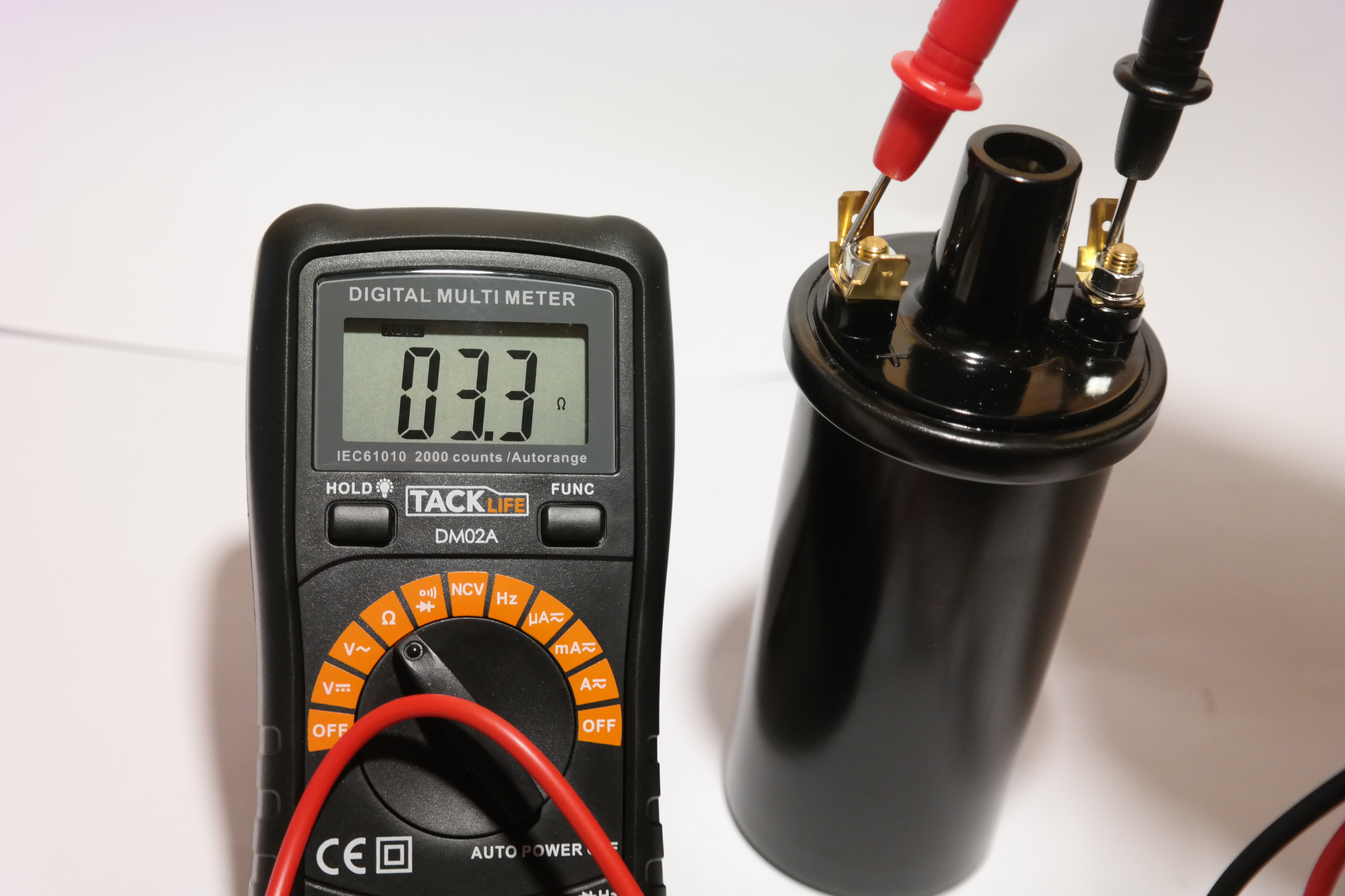
Measuring Resistance
Measuring resistance can indicate the health of a component. For example we can determine if an ignition coil is healthy or not by measuring the resistance of its windings. To measure resistance, set your meter to Ω ohms resistance. If you need to select a range, select the smallest range normally 200 ohms. Place the red probe onto one of the small terminals of the ignition coil, and the black one on the remaining small terminal. Your resistance will then display. A normal ignition coil should read about 3.5 to 4 ohms. If your meter reads a much higher resistance it means your ignition coil may have a short and is faulty.
Measuring Current
You can determine the amount of current being used and charged on your tractor’s system by placing the meter in-series with the circuits of the tractor. To do this: first remove your red probe and plug it into the 10 amp Max port on your DMM. Then set your DMM to DC Current with the range of 10 amps. Now you unplug the wire going to your ignition switch’s “B” terminal. By clipping alligator clips to your DMM probes you can now connect one probe to the “B” terminal of your ignition switch, and your other DMM probe to the wire that normally goes to “B” terminal on the ignition switch. Now when you run your tractor the current will flow through the meter and your DMM can give you a reading. It will tell you how many amps are flowing through your system.
Continuity Test
A great feature of many DMM’s is the continuity setting. The continuity function measures resistance, and if there is a complete connection the meter will give an audible beep. If there is no continuity your DMM will show “OL” on the display meaning there is an open line. You can use this to test for electrical shorts in wiring or components. I commonly use this function to quickly test for shorted ignition switches and ignition coils.

A Real World Example
Let’s say you attempt to start your tractor and your starter does not engage. No click of the solenoid, nothing happens at all. Before assuming your starter is bad, grab your DMM and set it to DC Volts. Remove the wire going to the small terminal of your starter solenoid and connect the red probe of your DMM to the wire. Now connect your black probe to a ground. Turn your tractor’s key. Your DMM reads no voltage. This tells you that power is not going from your battery to the solenoid. Next remove the wires from the back of your ignition switch that are connected to the “B” and “S” terminals on your switch. Set your DMM to Continuity and connect your probes to the “B” and “S” terminals of the switch. Turn your tractor’s key and if there is no “beep” you know your ignition switch has a short internally and should be replaced.
So that’s a basic overview of the Digital Multi-Meter and how you can use it to troubleshoot and repair the electrical system on your tractor.
Thank you for saving the tractors!
- Norman
Recent Posts
-

Engine Science: Rewind Your Small Tractor Engine Stator - Charging System Repair
Engine Science: How to Rewind Your Statorby Norman Ng, Founder of iSaveTractorsYour engine’s stator …Sep 10th 2020 -

Engine Science: The Digital Multi-Meter
The ability to detect, observe, and measure electricity is crucial when trying to understand how a …May 7th 2019 -

5 Common Small Engine Rebuilding Mistakes
The engine is the heart of your garden tractor. When performing heart surgery on your tractor, be aw …Jan 4th 2019