
Tractor Wiring Theory
We receive a lot of phone calls and emails from customers seeking help with their tractor issues. Some of the most common issues are related to the tractor’s wiring. It can be intimidating to look at a mess of different colored wires going in every direction, and try to make sense of it all. In this article, I will break down wiring theory and practices to its most simple and easy to understand form.
Before we dive into how our tractors are wired, let’s begin with some basic electrical wiring theory:
Circuit:
A circuit is a closed loop of wiring and components beginning at the positive side of the battery and ending back at the negative side of the battery. This loop is often closed using a common ground. Electricity only flows when a circuit is a closed loop. If the loop is open no electricity flows.
Common Ground:
A common ground is a path for electricity to flow back to the negative side of the battery. Most systems use the conductive metal on the engine block and tractor frame to lead electricity back to the negative side of the battery.
Volts:
Think of this as electrical pressure.
Amps:
Think of this as electrical volume. Amps can be determined by taking your voltage (12 volts) and dividing it by the resistance of a load. This is illustrated with the following formula: A = V/R
In-Series Wiring:
When something is wired “in series” it means it is wired in the middle of a circuit.
In-Parallel Wiring
When something is wired “in parallel” it means it is wired alongside a circuit with its own positive wire.
Now that we have a basic idea of electrical theory, let’s examine how it is all wired together. The example below illustrates wiring for an engine that uses battery ignition and a stator charging system.
The best way to look at your tractor’s wiring is to break it down into its four basic circuits: the starting circuit, ignition circuit, charging circuit and accessory circuit.
The starting Circuit
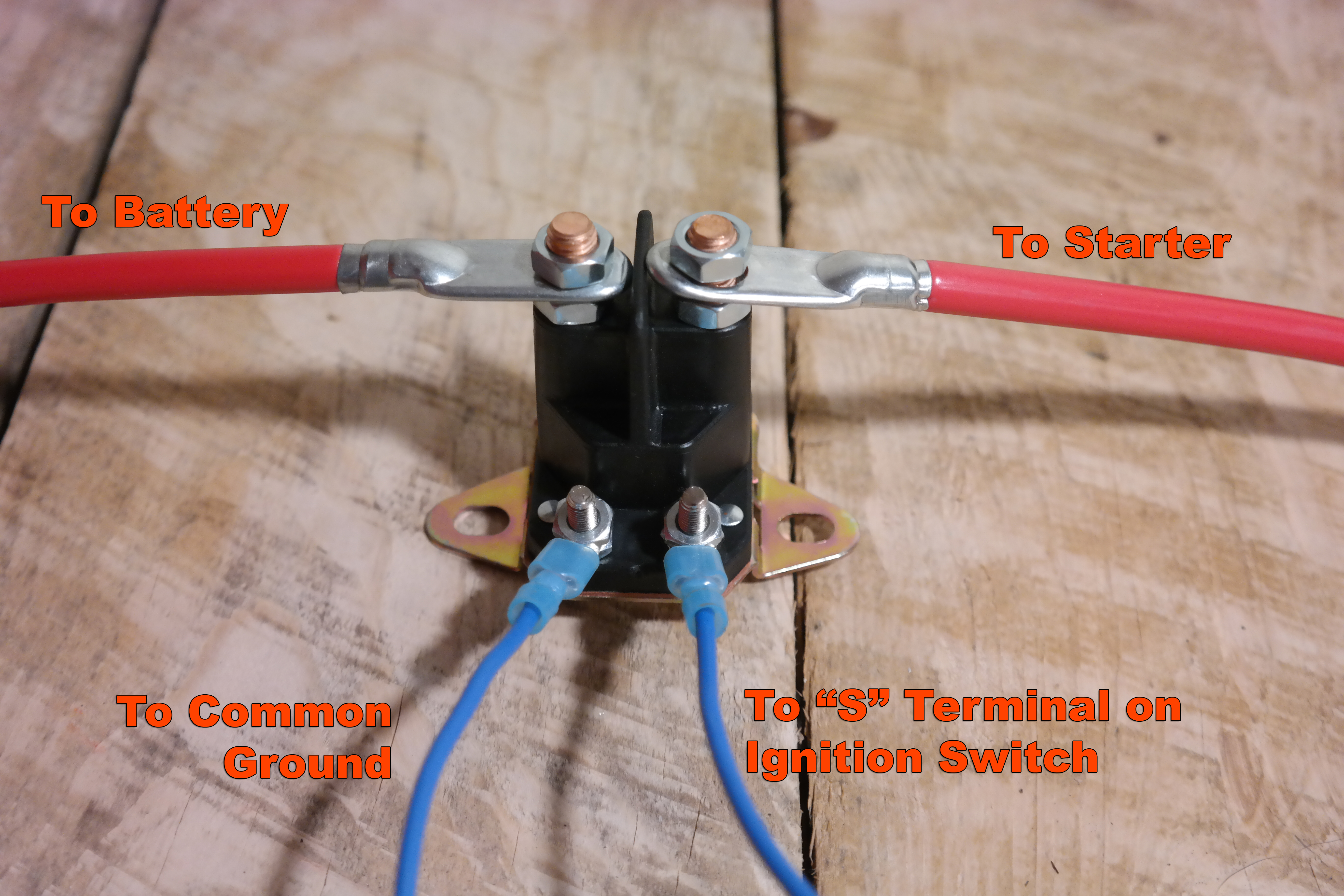
The starting circuit consists of your battery, ignition switch, starter solenoid, and starter.
Your ignition switch is a rotary switch that when turned to one of its 3 positions connects and disconnects certain contact terminals located on its backside. In the “start” position, it connects the Battery, Ignition, Rectifier, Accessory, and Start Terminals.
The starter solenoid is a relay switch that contains 2 circuits and has 3 or 4 wires connecting to and from it. Two of these wires are heavy gauge, and the remaining are smaller gauge. The two heavy gauge wires are connected to your starter and to your battery. The remaining small gauge wires are connected to the small terminals on the starter solenoid and lead to the ignition switch and to the common ground. If your starter solenoid only has one small wire or terminal, the ground is through the solenoid’s mounting bracket.
To turn your starter, electricity flows from the battery, through the ignition switch, and to the small terminals on the starter solenoid. This electricity causes an electromagnet inside the starter solenoid to connect the two heavy gauge wires and form a complete circuit. High amperage electric flow then goes through your starter, turning your engine’s flywheel.
The Ignition Circuit
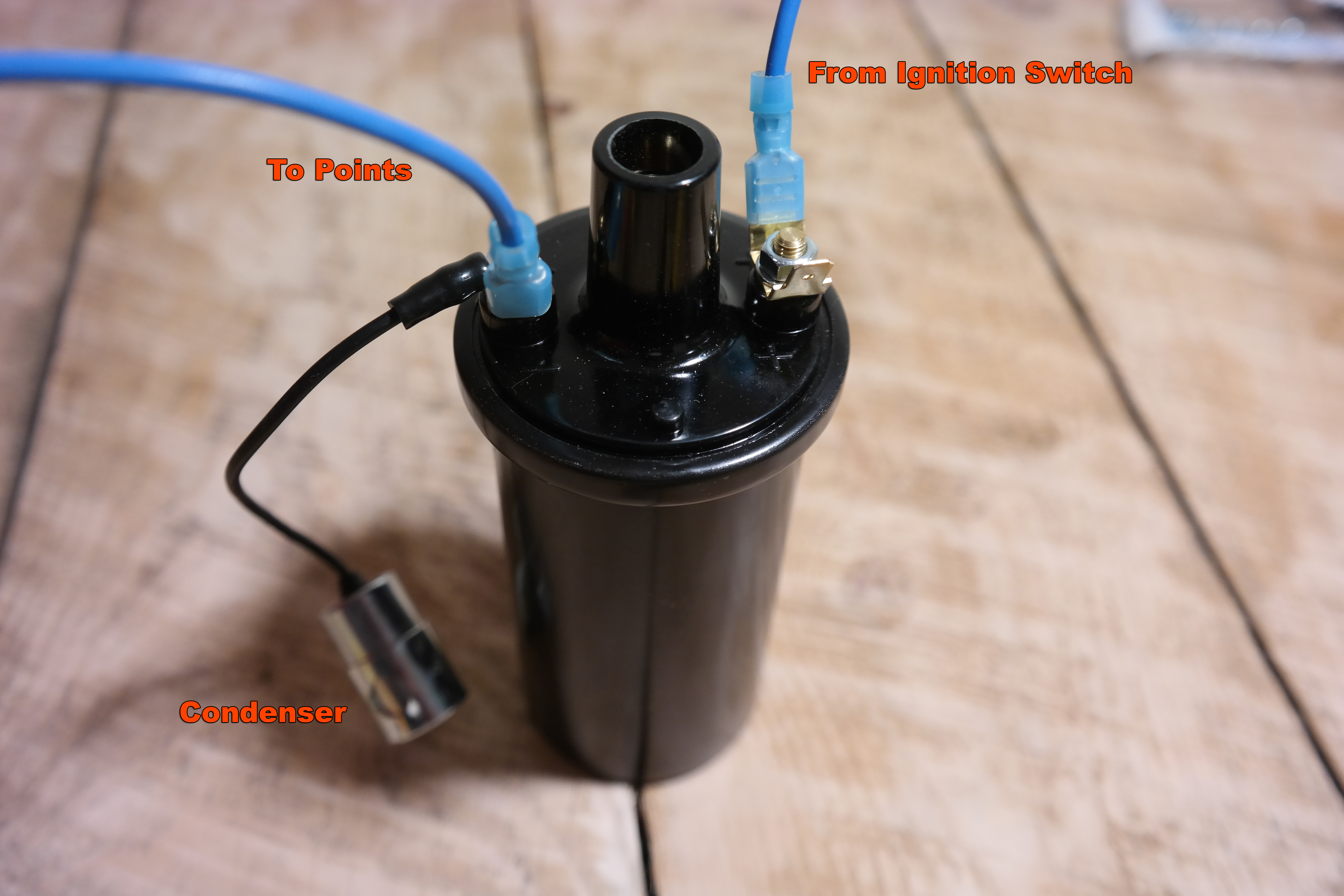
The ignition circuit consists of your battery, ignition switch, ignition coil, breaker points, condenser, and spark plug.
When your ignition switch is turned in the “start” and “run” position, the “I” or ignition terminal is energized and power flows from the battery through the primary winding of the ignition coil through the points and back to the engine ground. The primary winding of the ignition coil are the two small terminals marked + (positive) and – (negative). A small gauge wire goes from the ignition switch and connects to the + positive terminal of the ignition coil. The breaker points and condenser are both connected to the – (negative) terminal of the ignition coil. Your spark plug cable is connected to the secondary terminal which is the large wire port in the top of the ignition coil. Your spark plug is then connected to the high tension spark plug cable and screwed into your engine’s combustion chamber.
As your engine turns, the camshaft pushes your breaker points open, which creates a high voltage induction in your ignition coil. This high voltage power runs through your spark plug igniting your engine. Residual electricity in your ignition coil’s primary circuit is absorbed by the condenser.
The Charging Circuit
The charging circuit consists of your battery, ignition switch, rectifier/regulator, and stator.
When your engine is operating, your stator produces an alternating current by means of electromagnetic induction. This alternating current is fed to your rectifier/regulator by two wires. These two stator wires connect to the AC – and AC + terminals on the rectifier/regulator. The rectifier/regulator converts the alternating current into a direct current and is fed out of it through the terminal marked B+. This wire leads to the “rectifier or R” terminal on your ignition switch. This direct current charges your battery.
The Accessory circuit
The accessory circuit consists of your battery, ignition switch, a STSP switch and accessories such as an electric PTO, Headlights, Taillights, etc.
When your ignition switch is in the “run” position your accessory terminal is energized by the battery. Power then runs from the “A” or accessory terminal to a STSP (Single Throw Single Position) switch. This switch is wired in-series and is a way to connect and disconnect power to your accessory such as your headlights. Your headlights are then wired to the STSP light switch and are wired in parallel to each other. This means two wires will come from your light switch and connect to each headlight individually. Two ground wires will also come off each headlight individually and connect to the common ground. If you were to wire your headlights in series each headlight will only use 6 volts rather than 12 and the brightness will be diminished.
Making the connections
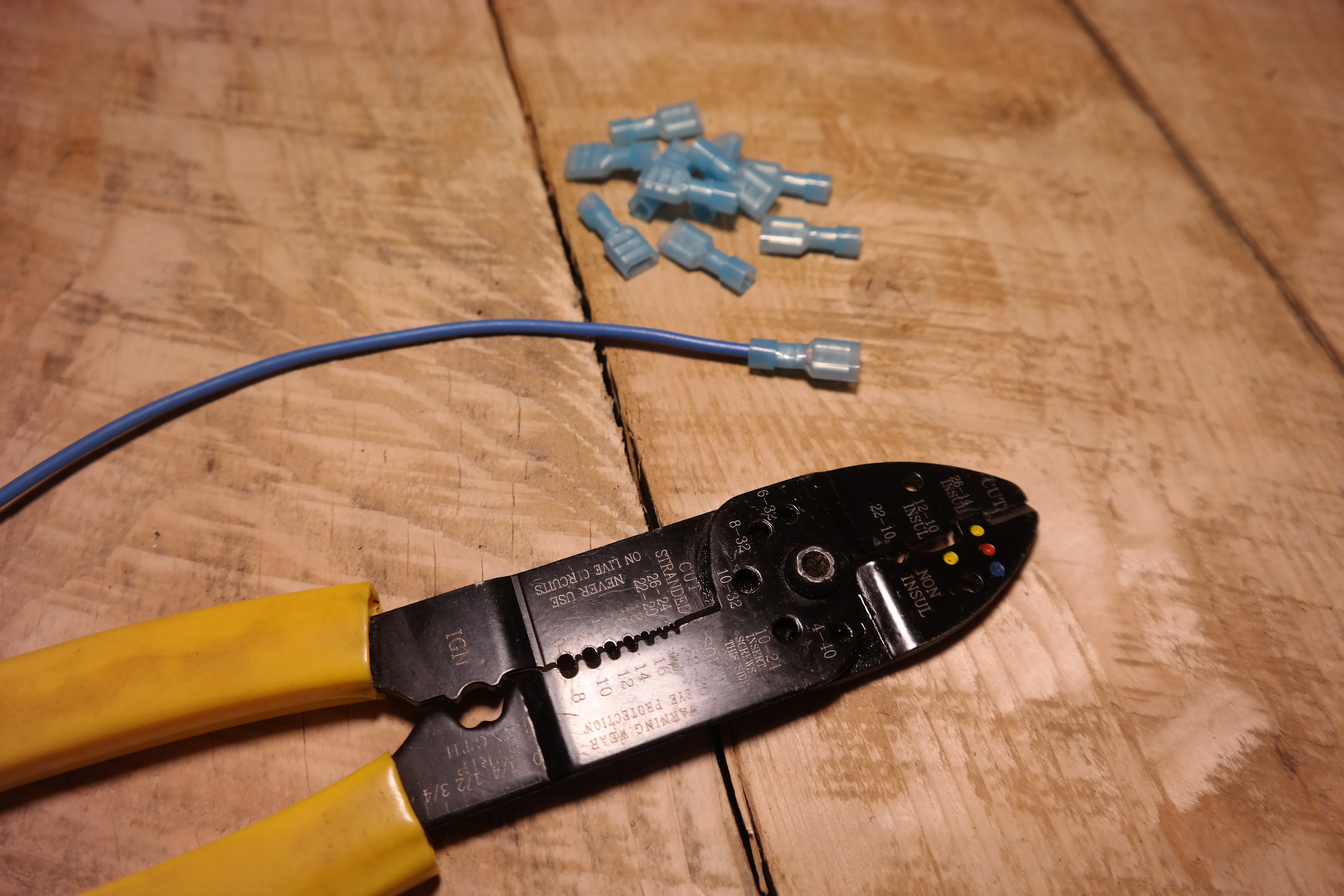
Most of the circuits in lawn and garden tractors use low amperage with the exception of the starting circuit. The wiring also only runs a short distance. I recommend using 6 AWG wire for the high amp starting circuit, and the negative side of the battery to common ground connection. All other wires can be 16 or 14 AWG. The easiest and most effective way to make all of the connections is by using nylon wire crimp connectors. Nylon wire crimp connectors are more durable than ones made from PVC. They are also easier to install than soldered connections. The most common crimp connectors you will use are spade and ring connectors.
I hope this basic explanation of tractor wiring helps you make sense of the tangled mess in your tractor. This was just a basic overview of wiring concepts. You can add additional components to your tractor such as safety switches, fuses, ammeters, hour meters, indicator lights, etc. They all will be wired in a similar fashion to above. The most important concept to remember is you need a closed loop or circuit to have electrical flow, and it’s best to visualize your wiring in separate circuits.
Thank you for saving the tractors,
- -Norman Ng
- www.isavetractors.com
Recent Posts
-
A Letter From the Owner of iSaveTractors
Dear Friends and Fellow Tractor Enthusiasts, After over a decade of serving the vintage small engine …Jun 5th 2025 -
Rebuild your Old Kohler K Series Engine vs Buying New
Why Rebuilding Your Old Kohler K-Series Engine Beats Buying a New Mower or Engine In today’s t …May 13th 2025 -
iSaveTractors vs Cheap Parts from Amazon
Why iSaveTractors Parts Outshine the Cheap Alternatives on Amazon When it comes to restoring and mai …May 12th 2025